Stages
Info
Patching
Segments
Ramp
Step
Hold
Single-Segment
Decay Envelope
LFO
Slew
Sample & Hold
CV Delay
Pulse Generator
General
Info
Stages
Stages is a versatile 6-segment signal generator by Mutable Instruments.
Some of this cheat-sheet is derived from the Mutable Instruments website, which is licensed CC-BY-SA-3.0.
Links
Stages HomeStages Manual
Patching
Grouping Segments
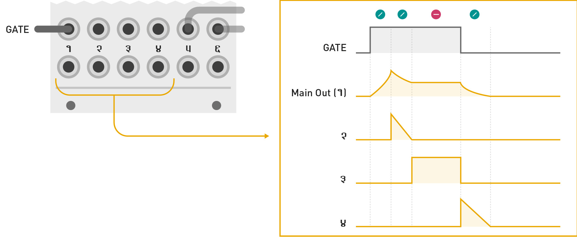
Complex modulations are built by grouping many segments into one modulation signal.
Inserting a jack in a GATE input marks the beginning of a group of segments. All unpatched segments at its right become part of this group.
Segment outputs
The first output of a group generates the envelope signal itself. The following outputs generate segment activity signals – ramps going from 8V to 0V whenever the corresponding segment is active.

Segment Rules

- The first RAMP segment ramps up to 8V, starting from whatever level the output currently stays at.
- The last RAMP segment ramps down to 0V.
- The level of a HOLD or STEP segment defines the start (end) level of the RAMP segment that follows (precedes) it. For example, in the preceding illustration, the end level of segment 3, and the start level of segment 5 are both set by the level of the HOLD segment 4.
- If the end level of a RAMP segment cannot be determined by rules 1, 2 or 3, this level is explicitly set by the potentiometer [A]. For example, in the preceding illustration, the end level of segments 2 and 5 are set by their potentiometer.
- If a LOOP is defined, the loop is played while the GATE signal is high. Once the GATE goes low, the envelope proceeds with the segment(s) that follow the loop end point. If the loop end is the last segment, there’s no escape from the loop, and the loop keeps going on forever.
- If the envelope contains a STEP segment, it follows its course normally until it gets trapped at the first STEP segment. It will stay at this segment until the next trigger is received. When this trigger is received, it will then proceed to the next segment… until the last segment or another STEP segment is reached. If an envelope contains a STEP segment inside a loop, there is no way of escaping this loop!
Segments
Ramp
Controls
|
Curve (Accelerating -> Linear -> Decelerating) |
Mode Green - Ramp | |
Ramp Time | |
Ramp Time | |
|
Trigger |
|
Description
The output glides to the target voltage with an adjustable slope, in the controlled amount of time. Start and end voltages are inferred, based on the segments coming before and after the Ramp segment. See 'Patching' for the full set of rules.Step
Controls
|
Glide Time |
Mode Orange - Step | |
Target Voltage | |
Target Voltage | |
|
Trigger |
|
Description
Step segments glide to the target voltage, and remain there until a trigger is received.
When used as a single segment, Step functions as a sample and hold.
Hold
Controls
|
Hold Time |
Mode Red - Hold | |
Target voltage | |
Target voltage | |
|
Trigger |
|
Description
The output stays at the same voltage for an adjustable duration, then the next segment is activated. Loop a Hold segment within an envelope for traditional 'Sustain' behaviour, holding at a specific value until the gate is low.Single-Segment
Decay Envelope
Controls
|
Curve (Accelerating -> Linear -> Decelerating) |
Mode Green - Ramp | |
Ramp Time | |
Ramp Time | |
|
Trigger |
|
Description
When used as a single-segment group, Ramp acts as a decay envelope with adjustable slope.LFO
Controls
|
Shape (see below) |
Mode Flashing Green - LFO | |
LFO Speed | |
LFO Speed | |
|
Clock (when patched) |
|
Description
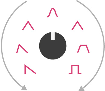
A looping single-segment Ramp acts as an LFO. The top potentiometer controls LFO shapes (see below).
When a clock source is patched into the Gate input, the LFO is tempo-synced. Stages can sync to a non-linear gate pattern as well.
LFO Shapes

Slew
Controls
|
Glide amount |
Mode Orange - Step | |
Voltage | |
Voltage | |
|
Leave unpatched |
|
Description
A single Step segment with trigger unpatched acts as a CV slew.Sample & Hold
Controls
|
Glide amount |
Mode Orange - Step | |
Voltage | |
Voltage | |
|
Trigger |
|
Description
A single Step segment with trigger patched acts as a Sample and Hold. The output will glide to the target voltage on the rising edge of an input trigger, with an adjustable amount of glide time.CV Delay
Controls
|
Delay Time |
Mode Red - Hold | |
Voltage | |
Voltage | |
|
Leave unpatched |
|
Description
A single Hold segment with trigger unpatched acts as a CV delay, delaying the input voltage (and slider) by an adjustable amount of time.Pulse Generator
Controls
|
Pulse Duration |
Mode Red - Hold | |
Pulse voltage | |
Pulse voltage | |
|
Trigger/Gate |
|